Naming Convention
Understanding Splicer requires a shared vocabulary to refer to its components, their spatial relationships, and the axes of motion involved. This chapter introduces the naming conventions used throughout the manual and in the development process. These conventions support clarity in documentation, collaboration, and troubleshooting.
System Overview
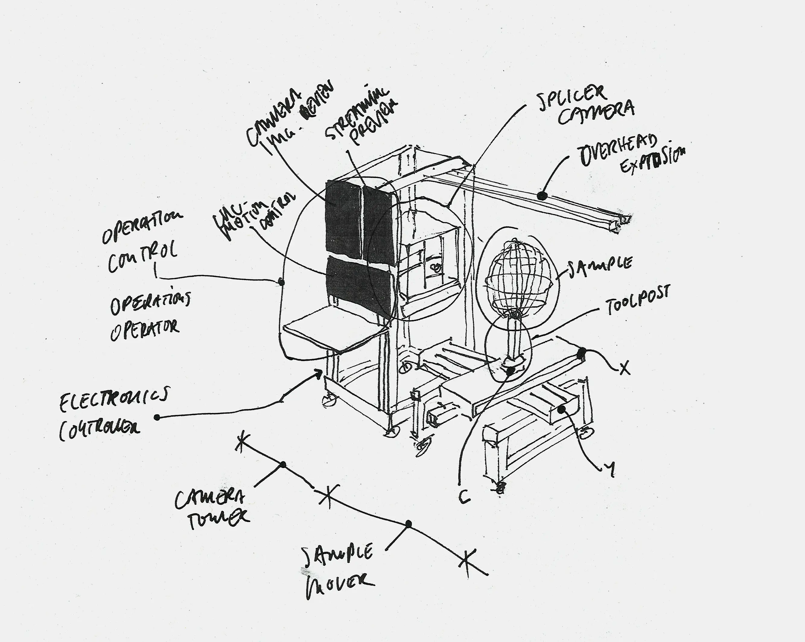
Overview of Splicer with key components annotated.
Splicer is composed of two primary modules:
Camera Tower
- Houses the Operation Control Interface and core imaging components.
- Contains the Z-axis, supporting the Splicer Camera Module v2.
- Equipped with three screens, arranged top left to bottom right: Camera Image Preview, Streaming Preview, CNC Motion Control
- At the top, two Overhead Extrusions extend forward: as structural supports for mounting lights, diffusers, and grip equipment.
Sample Mover
- Mechanically attached to the Camera Tower.
- Contains the XYC axis system for sample manipulation.
- At the center is the Toolpost, where the sample is mounted.
Axis Overview
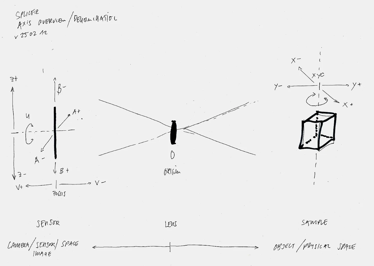
Axis overview and denomination.
The optical origin of Splicer is defined at the lensboard. While not the optical nodal point (which shifts depending on the lens used), the front surface of the lensboard is chosen as the fixed, consistent reference plane. If the nodal point were used, any lens change would alter the zero positions of the longitudinal axes, making consistent configuration files of the motion system impractical.
Image and Sensor Space
Located behind the lens, this zone includes: - The Camera Sensor - The ZUVAB axis system
Object and Physical Space
Located in front of the lens, this includes: - The Sample - The XYC axis system
From the perspective of the optical system, the lens remains static. All other components: the camera, sensor, and sample, move relative to it.