Electrical Wiring
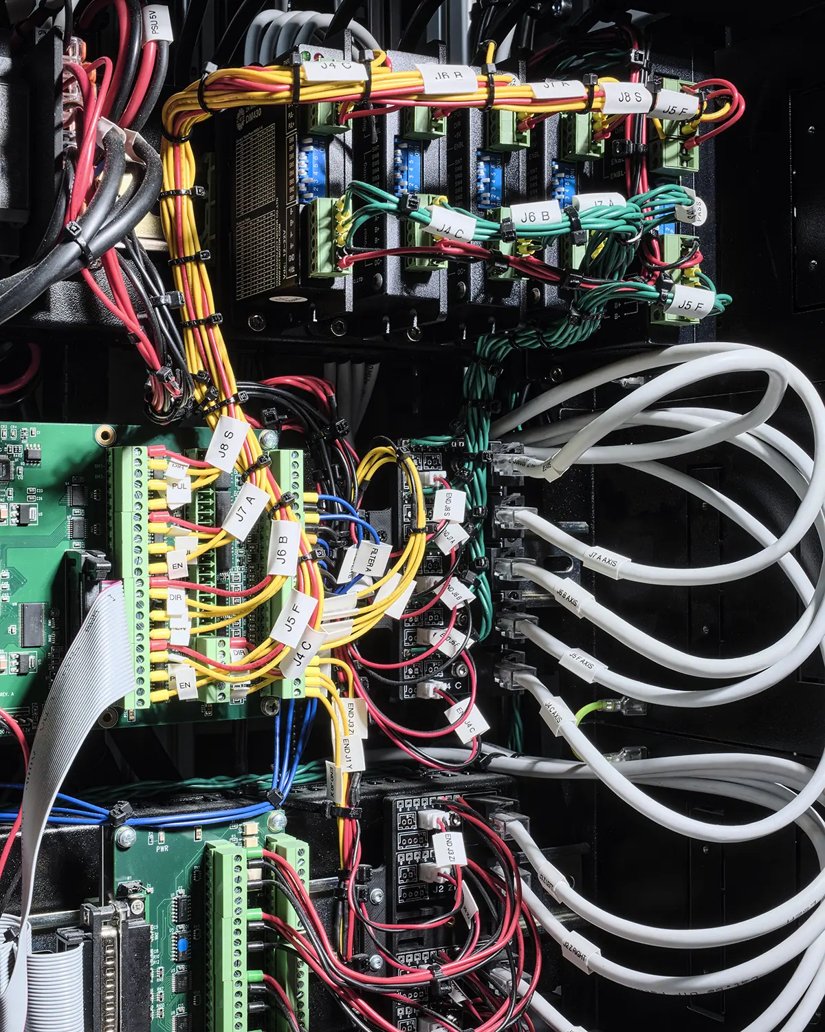
SPLICER / DEVELOPMENT, Wiring, Winter 2024
C-print, 40 × 50 cm
Splicer operates across four independent voltages, each serving distinct components of the apparatus. The separation of these layers is essential for maintaining signal integrity, safety, and operational stability.
- 48V: High-power servo motors (Sample mover and Z lift)
- 24V: Stepper motors, endstop switches, logic level triggers.
- 12V: Line scan sensor and sensor cooling system.
- 5V: Raspberry Pi (LinuxCNC motion controller)
Ensure each PSU is clearly labeled, fused, and verified before initial startup. All wiring connections must be made only while the machine is fully disconnected from mains power. Never connect or disconnect components with live voltage present.
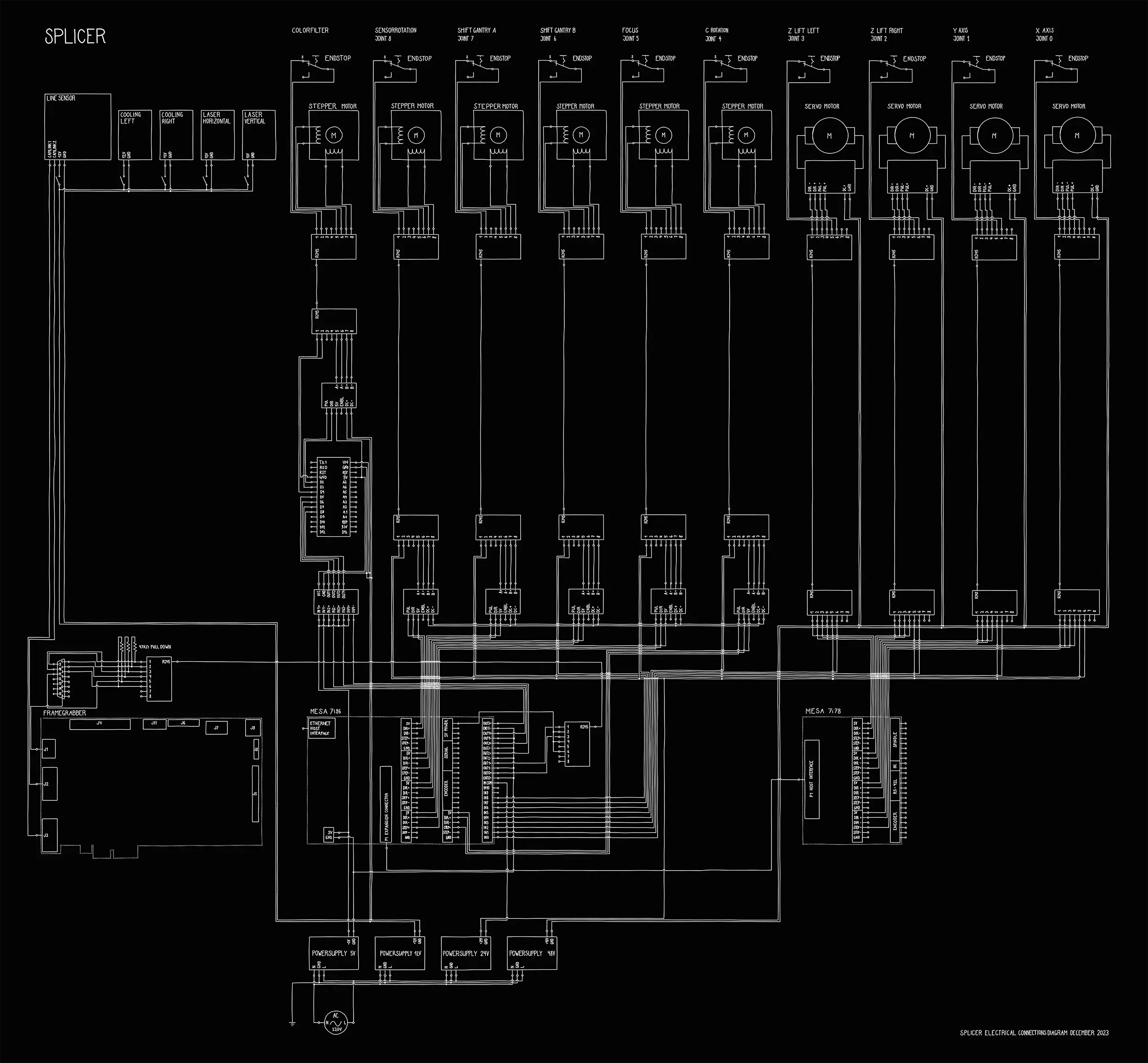
SPLICER / WIRING DIAGRAM, December 2023
White pen plot on 70 × 100 cm black cardboard

This piece functions simultaneously as a technical document
and an artwork. It presents a digitally hand-drawn wiring
diagram of Splicer, offering all necessary information for
electrical integration. Beyond its utilitarian purpose, the
diagram is a scaled representation of an internal aspect of
Splicer.