Axis Specification
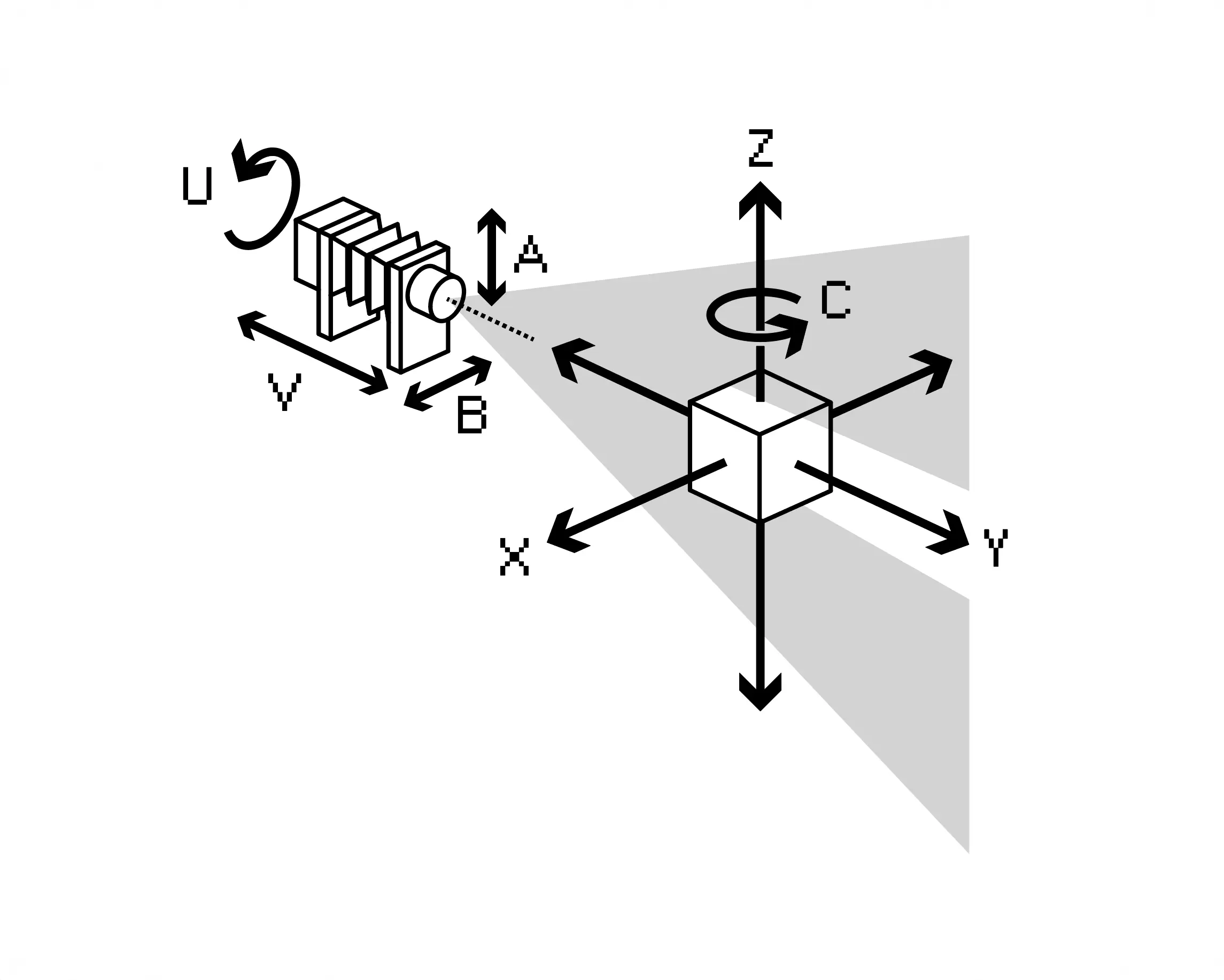
Each axis on Splicer is identified by a letter, a joint number, and a step generator (step-gen) number. The joint and step-gen numbers are primarily relevant during initial configuration or for debugging purposes. They are included here solely for the sake of completeness. The axis letters follow standard CNC axis naming conventions (A, B, C, X, Y, Z, U, V, W) and cannot be arbitrarily assigned.
This has no impact during normal operation.
Special cases include axes Z, A, and B. In software, Axis Z simultaneously controls two physical motors on the machine. Axes A and B in software control two motors via a CoreXY kinematic translation. The corresponding physical motors are also labeled A and B; however, they do not correspond to software axes A and B. This distinction is only relevant during the configuration of Splicer. Although the naming scheme is suboptimal, it cannot be changed due to the constraints of the CNC axis naming convention and the CoreXY naming convention.
X-Axis
| Joint | Step-gen | Units | Axis Origin | Min. Value | Max. Value |
|---|---|---|---|---|---|
0 |
5 |
mm |
Optical Centerline |
-254 |
254 |
From the perspective of the lens, X controls the left-to-right movement of the sample. Its origin is aligned with the optical centerline of the lens. X < 0 move the sample to the left, while X > 0 move it to the right.
Y-Axis
| Joint | Step-gen | Units | Axis Origin | Min. Value | Max. Value |
|---|---|---|---|---|---|
1 |
6 |
mm |
Lensboard |
130 |
1100 |
From the perspective of the lens, Y**controls the distance to the sample. Its origin is located at the lens board of Splicer. Smaller values position the sample closer to the lens, while larger values move it farther away. TheY-Axis` corresponds to the depth dimension in the captured image.
Z-Axis
| Joint (Z-Motor Right) | Step-gen (Z-Motor Right) | Units | Axis Origin | Min. Value | Max. Value |
|---|---|---|---|---|---|
2 |
7 |
[mm] |
Lensboard |
-100 |
440 |
| Joint (Z-Motor Left) | Step-gen (Z-Motor Left) | Units | Axis Origin | Min. Value | Max. Value |
|---|---|---|---|---|---|
3 |
8 |
[mm] |
Lensboard |
-100 |
440 |
From the perspective of the lens, Z controls the vertical position (height) of the sample. Its origin lies along the optical centerline of the lens, at the top side of the sample post. Negative values position the camera below the sample; positive values position it above. When the line sensor is in vertical orientation (U = 0), the Z Axis corresponds to the vertical position of the sample in the captured image.
A-Axis, B-Axis
A and B refer to different things in software and hardware
Axis A (software) does not directly correspond to Motor A due to the use of CoreXY kinematics. Axis B**` (software) is also abstracted in the same way. Always refer to the configuration documentation when working with AB axes to avoid confusion.
A-Axis
| Joint (A-Motor) | Step-gen (A-Motor) | Units | Axis Origin | Min. Value | Max. Value |
|---|---|---|---|---|---|
6 |
1 |
mm |
Optical Axis |
-105 |
105 |
B-Axis
| Joint (B-Motor) | Step-gen (B-Motor) | Units | Axis Origin | Min. Value | Max. Value |
|---|---|---|---|---|---|
7 |
2 |
mm |
Optical Axis |
-80 |
80 |
From the perspective of the lens:
Arepresents the vertical optical shiftBrepresents the horizontal optical shift
Both axes originate at the optical centerline. The coordinate system follows a standard XY convention, with positive and negative values corresponding to the four quadrants:
A > 0,B > 0: Shift towards Quadrant I (upwards and right)A < 0,B > 0: Shift towards Quadrant II (downwards and right)A < 0,B < 0: Shift towards Quadrant III (downwards and left)A > 0,B < 0: Shift towards Quadrant IV (upwards and left)
This design aligns logically with the physical space in front of the lens, specifically the side where the sample is located within the Splicer system. Behind the lens, the axes and coordinates are mirrored and flipped, as the projected image is also inverted by the lens.
For example, a command to “look up” (i.e., a positive shift on Axis A) results in the sensor moving downward. This is analogous to shifts on the back standard of a large format camera, where the image plane moves while the lens remains stationary.
C-Axis
| Joint | Step-gen | Units | Axis Origin | Min. Value | Max. Value |
|---|---|---|---|---|---|
4 |
4 |
Degrees |
Vertical Axis of Sample |
-3600 |
3600 |
From the perspective of the lens, C controls the rotation of the sample around the vertical axis. Positive values rotate the sample clockwise; negative values rotate it counterclockwise.
U-Axis
| Joint | Step-gen | Units | Axis Origin | Min. Value | Max. Value |
|---|---|---|---|---|---|
8 |
4 |
Degrees |
Vertical Orientation |
-200° |
+200° |
Rotating the sensor ALWAYS requires supervision of the sensor cables.
U controls the orientation of the sensor line. A value of U = 0 aligns the sensor vertically. Positive values of U rotate the sensor clockwise. Negative values of U rotate the sensor counterclockwise. A value of U = 90 results in a horizontal orientation. Care must be taken to monitor cable tension and routing behind the sensor carriage at all times during rotation to prevent damage.
V-Axis
| Joint | Step-gen | Units | Axis Origin | Min. Value | Max. Value |
|---|---|---|---|---|---|
5 |
0 |
mm |
Lensboard |
53 |
275 |
V controls the autofocus mechanism of Splicer.
Its origin is located at the lens board of Splicer. Smaller values move the sensor closer to the lens, shifting the focus toward infinity. Larger values move the sensor farther from the lens, bringing the focus closer.
A classic rule of thumb from large format photography applies:
- At infinity focus, the focus distance equals the focal length of the lens.
- At 1:1 magnification (where the projected image matches the object's physical size), the focus distance equals 2× the focal length.
In standard use, V is set automatically by the splicer-animator script at export and does not require manual adjustment. Its value is derived from the current Y-Axis position and the configured focus-offset parameter in the splicer-animator for the corresponding line.